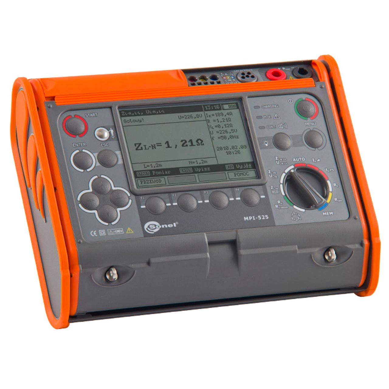
Description Electrical Installation Multi-function Meter MPI-525 Technical Specifications Rated operational conditions: – Operation temperature 0 – 50°C Electric security: – Type of insulation: double, according to PN-EN 61010 – 1 And IEC 61557, EMC – Measurement category: IV 300 V acc. to PN-EN 61010 – 1 – Protection class acc. to PN-EN 60529: IP54 Measurement of short circuit loop impedance ZL-PE, ZL-N, ZL-L Test current: 23/40 A; Measuring range acc. to IEC 61557: 0,13 – 1999,9 Ω (for 1.2 m test lead): Display range Resolution Accuracy 0,000 – 19,999 Ω 0,001 Ω ±(5% m.v. 30 digits) 20,00 – 199,99 Ω 0,01 Ω ±(5% m.v. 30 digits) 200,0 – 1999,9 Ω 0,1 Ω ±(5% m.v. 30 digits) Rated voltage: 95 – 270 V (for ZL-PE and ZL-N) and 95 – 440 V (for ZL-L) Frequency: 45 – 65 Hz Measurement of short circuit loop impedance ZL-PE in RCD mode Test current: 15 mA, measuring range acc. to IEC 61557: 0,50 – 1999 Ω Display range Resolution Accuracy 0,00 – 19,99 Ω 0,01 Ω ±(6% m.v. 10 digits) 20,0 – 199,9 Ω 0,1 Ω ±(6% m.v. 5 digits) 200 – 1999 Ω 1 Ω ±(6% m.v. 5 digits) Rated voltage: 95 – 270 V Frequency: 45 – 65 Hz Measurement of earth resistance RE Measuring range acc. to IEC 61557-5: 0,50 Ω -1999 Ω Display range Resolution Accuracy 0,00 – 9,99 Ω 0,01 Ω ±(2% m.v. 4 digits) 10,0 – 99,9 Ω 0,1 Ω ±(2% m.v. 3 digits) 100 – 999 Ω 1 Ω ±(2% m.v. 3 digits) 1,00 – 1,99 kΩ 0,01 kΩ ±(2% m.v. 3 digits) Insulation resistance measurements Measuring range acc. to IEC 61557-2: For UN= 50 V: 50 kΩ- 250 MΩ UN = 100 V: 100 kΩ – 500 MΩ UN = 250 V: 250 kΩ – 999 MΩ For UN = 500 V: 500 kΩ – 2 GΩ UN = 1000 V: 1 MΩ – 9,99 GΩ UN = 2500 V: 2,5 MΩ – 9,99 GΩ Display range * Resolution Accuracy 0,00 – 1999 kΩ 1 kΩ ±(3% m.v. 8 digits) 2,00 – 19,99 MΩ 0,01 MΩ ±(3% m.v. 8 digits) 20,0 – 199,9 MΩ 0,01 MΩ ±(3% m.v. 8 digits) 200 – 999 MΩ 1 MΩ ±(3% m.v. 8 digits) 1,00 – 3,00 GΩ 0,01 GΩ ±(4% m.v. 6 digits) 3,00 – 9,99 GΩ 0,1 GΩ ±(4% m.v. 6 digits) *Limited to measurement range. -With UNI-Schuko additional error ±2 % Phase sequence – Phase sequence indicator: forward, reverse – Mains voltage range UL-L: 100 – 440 V (45 – 65 Hz) UL-L: 100 – 440 V (45 – 65 Hz) – Display of phase-to-phase voltages Low-voltage test of the circuit and insulation continuity Test of PE wire continuity using ±200 mA current Display range Resolution Accuracy 0,00 – 19,99 Ω 0,01 Ω ±(2% m.v. 3 digits) 20,0 – 199,9 Ω 0,1 Ω ±(2% m.v. 3 digits) 200 – 400 Ω 1 Ω ±(2% m.v. 3 digits) Voltage on open terminals: 4 – 9 V Test current at R < 2 Ω: min. 200 mA at rated battery voltage Autocalibration of test leads Measurements for both polarizations of the current RCD trigger and response time test tA(for tA mode): Measurement ranges in accordance with IEC 61557: 0 ms – up to the upper bound of the displayed value Breaker Type Test Current Multiplier Range Resolution Accuracy Standard 0,5*IΔn 0 – 300 ms 1 ms ±(2% m.v. 2 digits) Standard 1*IΔn 0 – 300 ms 1 ms ±(2% m.v. 2 digits) Standard 2*IΔn 0 – 150 ms 1 ms ±(2% m.v. 2 digits) Standard 5*IΔn 0 – 40 ms 1 ms ±(2% m.v. 2 digits) Selective 0,5*IΔn 0 – 500 ms 1 ms ±(2% m.v. 2 digits) Selective 1*IΔn 0 – 200 ms 1 ms ±(2% m.v. 2 digits) Selective 2*IΔn 0 – 200 ms 1 ms ±(2% m.v. 2 digits) Selective 5*IΔn 0 – 150 ms 1 ms ±(2% m.v. 2 digits) Precision of the differential current: for 0,5*IΔn:-8 – 0% | for 1*IΔn | 2*IΔn | 5*IΔn: 0 – 8% Measurement of the RCD triggering current (IA) for sine waveform testing current Selected current Meas. range Resolution Test current Accuracy 10 mA 3,3 – 10,0 mA 0,1 mA 0,3 x IΔn – 1,0 x IΔn ± 5% IΔn 30 mA 9,0 – 30,0 mA 0,1 mA 0,3 x IΔn – 1,0 x IΔn ± 5% IΔn 100 mA 33 – 100 mA 1 mA 0,3 x IΔn – 1,0 x IΔn ± 5% IΔn 300 mA 90 – 300 mA 1 mA 0,3 x IΔn – 1,0 x IΔn ± 5% IΔn 500 mA 150 – 500 mA 1 mA 0,3 x IΔn – 1,0 x IΔn ± 5% IΔn 1000 mA 330 – 1000 mA 1 mA 0,3 x IΔn – 1,0 x IΔn ± 5% IΔn It is possible to start the measurement from the positive or negative half of the forced leaking current Measurement of RCD tripping current (IA) for a unidirectional half-period sine waveform test current with a 6 mA DC offset Selected current Meas. range Resolution Test current Accuracy 10 mA 4 – 20,0 mA 0,1 mA 0,4 x IΔn – 2,0 x IΔn ±10%IΔn 30 mA 12,0 – 42,0 mA 0,1 mA 0,4 x IΔn – 1,4 x IΔn ±10%IΔn 100 mA 40,0 – 140 mA 1 mA 0,4 x IΔn – 1,4 x IΔn ±10%IΔn 300 mA 120 – 420 mA 1 mA 0,4 x IΔn – 1,4 x IΔn ±10%IΔn 500 mA 200 – 700 mA 1 mA 0,4 x IΔn – 1,4 x IΔn ±10%IΔn Measurement is possible for positive or negative forced leakage current Measurement of RCD tripping current (IA) for direct residual current Selected current Meas. range Resolution Test current Accuracy 10 mA 4 – 20,0 mA 0,1 mA 0,4 x IΔn – 2,0 x IΔn ±10%IΔn 30 mA 12,0 – 42,0 mA 0,1 mA 0,4 x IΔn – 2,0 x IΔn ±10%IΔn 100 mA 40,0 – 140 mA 1 mA 0,4 x IΔn – 2,0 x IΔn ±10%IΔn 300 mA 120 – 420 mA 1 mA 0,4 x IΔn – 2,0 x IΔn ±10%IΔn 500 mA 200 – 700 mA 1 mA 0,4 x IΔn – 2,0 x IΔn ±10%IΔn Measurement is possible for a positive or negative forced leakage current Calibration certificates are issued during the production process. New calibration certificates are available upon request at an additional cost. NOTE: “m.v.” – measured value.