Hot
New Arrival
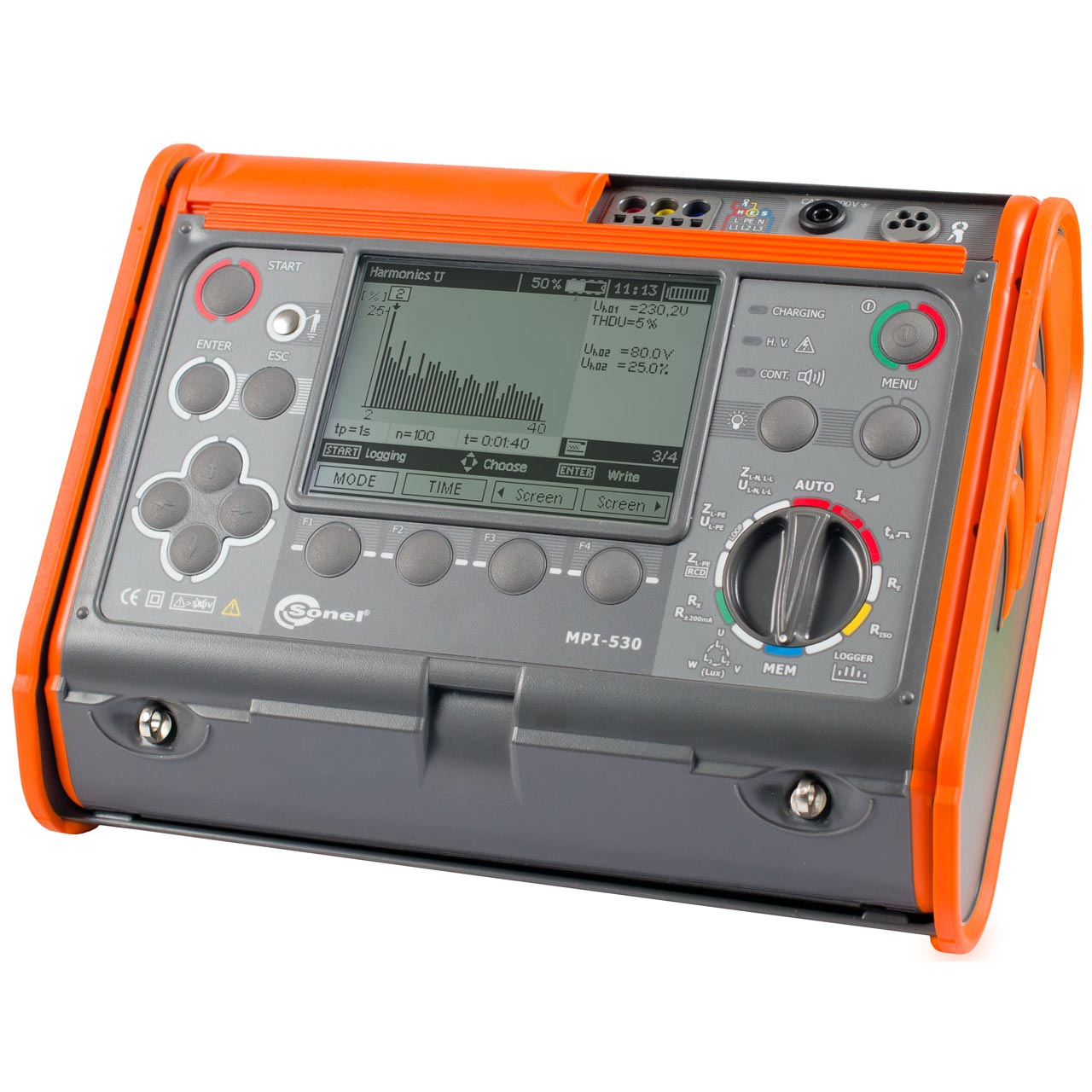
Electrical Installation Multi-function Meter | MPI-530
Description Electrical Installation Multi-function Meter MPI-530 Technical Specifications Measurement of short circuit loop impedance: Impedance measurement with resolution 0,001 Ω and 23 A current (44 A phase-to-phase) – short-circuit resistor RZW = 10 Ω Measurement range: 95 – 440 V, Frequency 45 – 65 Hz Measurement of short circuit loop impedance with resolution 0,01 Ω, in protected systems without tripping the RCD’s with IΔn ≥ 30 mA Automatic calculation of short-circuit current, differentiating between phase-to-phase and phase-to-neutral voltage Measurements using UNI-Schuko plug with measurement triggering button (also when L and N leads are exchangeable) or 1,2 m, 5 m, 10 m, 20 m test leads, with optional use of 3-phase socket adapters (AGT) Selection of installation protections and automatic evaluation of measurement results Tests of residual current devices (RCD), types AC, A, F, B, and B : Measurement of general, short-time delay and selective RCD’s with the rated residual current of 10, 30, 100, 300, 500, and 1000 mA Automatic measurement of all RCD parameters (when the START button is pressed, the meter performs the whole measurement cycle, including the L-PE short circuit loop impedance measurement with 15 mA current), A user selected waveform of forced leakage current: sinusoidal (start from increasing or decreasing edge), unidirectional pulsating (positive or negative), unidirectional pulsating with DC bias (positive and negative), direct (positive and negative) The measurement of tripping current IA using the ramp current Measurement of tripping time tA at ½IΔn, 1IΔn, 2IΔn, and 5IΔn Measurement of touch voltage UB and protective conductor resistance RE without the RCD tripping Detection that L and N conductors are switched in the socket; will not affect the measurement Measurement of tripping current IA and actual tripping time tAI at single activation of RCD Measurement for 95 – 70 V voltage Insulation resistance measurements: Test voltage values: 50 V, 100 V, 250 V, 500 V and 1000 V Insulation resistance measurements up to 10 GΩ In-socket measurements using the UNI-Schuko adapter Meter is protected against voltage on the tested object and voltage appearing during the measurement Auto-discharge of the object after the measurement Automatic measurement of all resistance combinations in three-, four- and five core leads using the additional AutoISO-1000C adapter Acoustic signaling of five-second periods to enable determining the time profile during the insulation resistance measurements Low-voltage resistance measurement of equipotential and protective bonding: Continuity measurement of protective conductor with ≥200 mA current in both directions Low current measurement with the sound signal Autocalibration of test leads – leads of any length can be used Earth resistance measurements: Measurement with 3- and 4-pole methods with 2 Additional electrodes The measurement with the 3-pole method with an additional clamp Measurement with the 2-clamp method Soil resistivity measurements. Illuminance measurements. A quick check of PE connection correctness. Measurement and recording of voltage, frequency, AC, cosφ and power (active, reactive and apparent), voltage and current harmonics up to 40, THD. Checking reactive phase sequence and motor direction of rotation. Innovative memory with the possibility of a description of measurement points, facilities, names of customers. Power supply from rechargeable disposable batteries (optional) The meter conforms to EN 61557. Measurement of short circuit loop impedance ZL-PE, ZL-N, ZL-L Test current: 23/40 A; measuring range acc. to IEC 61557: 0,13 – 1999,9 Ω (for 1.2 m test lead): Display range Resolution Accuracy 0,000 – 19,999 Ω 0,001 Ω ±(5% m.v. 30 digits) 20,00 – 199,99 Ω 0,01 Ω ±(5% m.v. 30 digits) 200,0 – 1999,9 Ω 0,1 Ω ±(5% m.v. 30 digits) Rated voltage: 95 – 270 V (for ZL-PE and ZL-N) and 95 – 440 V (for ZL-L) Frequency: 45 – 65 Hz Measurement of short circuit loop impedance ZL-PE in RCD mode Test current: 15 mA, measuring range acc. to IEC 61557: 0,50 – 1999 Ω Display range Resolution Accuracy 0,00 – 19,99 Ω 0,01 Ω ±(6% m.v. 10 digits) 20,0 – 199,9 Ω 0,1 Ω ±(6% m.v. 5 digits) 200 – 1999 Ω 1 Ω ±(6% m.v. 5 digits) Rated voltage: 95 – 270 V Frequency: 45 – 65 Hz Measurement of earth resistance RE with the 3p and 4p method Measuring range acc. to IEC 61557-5: 0,50 Ω -1,99 kΩ for test voltage 50 V| 50 Ω – 1,99 kΩ for test voltage 25 V Display range Resolution Accuracy 0,00 – 9,99 Ω 0,01 Ω ±(2% m.v. 4 digits) 10,0 – 99,9 Ω 0,1 Ω ±(2% m.v. 3 digits) 100 – 999 Ω 1 Ω ±(2% m.v. 3 digits) 1,00 – 1,99 kΩ 0,01 kΩ ±(2% m.v. 3 digits) Test voltage: 25 V or 50 V rms Test current: 20 mA, sinusoidal rms 125 Hz (for fn= 50 Hz) and 150 Hz (for fn= 60 Hz) Measurement blocked at interference voltage UN> 24 V Maximum measured interference voltage Unmax= 100 V Maximum resistance of auxiliary earth electrodes 50 kΩ Selective earth resistance measurement with clamp (3p clamp) Measuring range acc. to IEC 61557-5: 1 – 1,99 kΩ Display range Resolution Accuracy 0,00 – 9,99 Ω 0,01 Ω ±(2% m.v. 4 digits) 10,0 – 99,9 Ω 0,1 Ω ±(2% m.v. 4 digits) 100 – 999 Ω 1 Ω ±(2% m.v. 4 digits) 1,00 – 1,99 kΩ 0,01 kΩ ±(2% m.v. 4 digits) Measurement with additional current clamp Interference current measuring range: up to 9,99 A Selective earth measurement with two clamps Display range Resolution Accuracy 0,00 – 9,99 Ω 0,01 Ω ±(10% m.v. 4 digits) 10,0 – 19,9 Ω 0,1 Ω ±(10% m.v. 4 digits) 20,0 – 99,9 Ω 0,1 Ω ±(20% m.v. 4 digits) Measurement with transmitting and receiving clamps Interference current measuring range: up to 9,99 A Soil resistivity measurement (ρ) Display range Resolution Accuracy 0,00 – 99,9 Ωm 0,1 Ωm Depending on the accuracy of RE measurement 100 – 999 Ωm 1 Ωm Depending on the accuracy of RE measurement 1,00 – 9,99 Ωm 0,01 kΩm Depending on the accuracy of RE measurement 10,0 – 99,9 kΩm 0,1 kΩm Depending on the accuracy of RE measurement Measurement with Wenner’s method Distance settable in meters or feet Distance range: 1 – 30 m (1 – 90 feet) Phase sequence indication Phase sequence indication: conforming, non-conforming Mains voltage range U: 100 – 440 V (45 – 65 Hz) L-L Display of phase-to-phase voltage values Measurements of RCD parameters(voltage range 95 – 270 V): RCD tripping test and measurement of tripping time tA(for tA measurement function) RCD type Current Range Resolution Accuracy General and short-time delay 0,5*IΔn 0 – 300 ms 1 ms ±(2% m.v. 2 digits) (for RCD with IΔn = 10 mA and 0,5xIΔn uncertainty: ±(2% m.v. 3 digits) General and short-time delay 1*IΔn 0 – 300 ms 1 ms ±(2% m.v. 2 digits) (for RCD with IΔn = 10 mA and 0,5xIΔn uncertainty: ±(2% m.v. 3 digits) General and short-time delay 2*IΔn 0 – 150 ms 1 ms ±(2% m.v. 2 digits) (for RCD with IΔn = 10 mA and 0,5xIΔn uncertainty: ±(2% m.v. 3 digits) General and short-time delay 5*IΔn 0 – 40 ms 1 ms ±(2% m.v. 2 digits) (for RCD with IΔn = 10 mA and 0,5xIΔn uncertainty: ±(2% m.v. 3 digits) Selective 0,5*IΔn 0 – 500 ms 1 ms ±(2% m.v. 2 digits) (for RCD with IΔn = 10 mA and 0,5xIΔn uncertainty: ±(2% m.v. 3 digits) Selective 1*IΔn 0 – 200 ms 1 ms ±(2% m.v. 2 digits) (for RCD with IΔn = 10 mA and 0,5xIΔn uncertainty: ±(2% m.v. 3 digits) Selective 2*IΔn 0 – 200 ms 1 ms ±(2% m.v. 2 digits) (for RCD with IΔn = 10 mA and 0,5xIΔn uncertainty: ±(2% m.v. 3 digits) Selective 5*IΔn 0 – 150 ms 1 ms ±(2% m.v. 2 digits) (for RCD with IΔn = 10 mA and 0,5xIΔn uncertainty: ±(2% m.v. 3 digits) Accuracy of residual current application: for 0,5*IΔn:-8 – 0% | for 1*IΔn | 2*IΔn | 5*IΔn: 0 – 8% Measurement of RCD tripping current IΔnfor sinusoidal residual current (AC type) Rated current Meas. range Resolution Test current Accuracy 10 mA 3,3 – 10,0 mA 0,1 mA 0,3 x IΔn – 1,0 x IΔn ± 5% IΔn 30 mA 9,0 – 30,0 mA 0,1 mA 0,3 x IΔn – 1,0 x IΔn ± 5% IΔn 100 mA 33 – 100 mA 1 mA 0,3 x IΔn – 1,0 x IΔn ± 5% IΔn 300 mA 90 – 300 mA 1 mA 0,3 x IΔn – 1,0 x IΔn ± 5% IΔn 500 mA 150 – 500 mA 1 mA 0,3 x IΔn – 1,0 x IΔn ± 5% IΔn 1000 mA 330 – 1000 mA 1 mA 0,3 x IΔn – 1,0 x IΔn ± 5% IΔn The measurement can be started from a positive or negative half-period of forced leakage current Measurement of RCD tripping current IA for unidirectional residual current and unidirectional with the 6 mA DC bias (type A) Rated current Meas. range Resolution Test current Accuracy 10 mA 3,5 – 20,0 mA 0,1 mA 0,35 x IΔn – 2,0 x IΔn ±10%IΔn 30 mA 10,5 – 42,0 mA 0,1 mA 0,35 x IΔn – 1,4 x IΔn ±10%IΔn 100 mA 35,0 – 140 mA 1 mA 0,35 x IΔn – 1,4 x IΔn ±10%IΔn 300 mA 105 – 420 mA 1 mA 0,35 x IΔn – 1,4 x IΔn ±10%IΔn 500 mA 175 – 700 mA 1 mA 0,35 x IΔn – 1,4 x IΔn ±10%IΔn Measurement for positive or negative half-periods of forced leakage current Measurement of RCD tripping current I for direct residual current (type B) Rated current Meas. range Resolution Test current Accuracy 10 mA 2,0 – 20,0 mA 0,1 mA 0,2 x IΔn – 2,0 x IΔn ± 10% IΔn 30 mA 6 – 60 mA 1 mA 0,2 x IΔn – 2,0 x IΔn ± 10% IΔn 100 mA 20 – 200 mA 1 mA 0,2 x IΔn – 2,0 x IΔn ± 10% IΔn 300 mA 60 – 600 mA 1 mA 0,2 x IΔn – 2,0 x IΔn ± 10% IΔn 500 mA 100 – 1000 mA 1 mA 0,2 x IΔn – 2,0 x IΔn ± 10% IΔn Measurement for positive or negative half-periods of forced leakage current IΔn– rated residual current Insulation resistance measurements Measuring range acc. to IEC 61557-2: For UN= 50 V: 50 kΩ- 250 MΩ UN= 100 V: 100 kΩ – 500 MΩ UN= 250 V: 250 kΩ – 999 MΩ For UN= 500 V: 500 kΩ – 2 GΩ For UN= 1000 V: 1,000 MΩ – 9,99 GΩ Display range * Resolution Accuracy 0,00 – 1999 kΩ 1 kΩ ±(3% m.v. 8 digits) 2,00 – 19,99 MΩ 0,01 MΩ ±(3% m.v. 8 digits) 20,0 – 199,9 MΩ 0,01 MΩ ±(3% m.v. 8 digits) 200 – 999 MΩ 1 MΩ ±(3% m.v. 8 digits) 1,00 – 9,99 GΩ 0,01 GΩ ±(4% m.v. 6 digits) *not greater than measuring range for given voltage Low-voltage measurement of resistance and circuit continuity Measurement of protective conductor continuity with the ±200 mA current, IEC 61557-4: 0,12 – 400 Ω Display range Resolution Accuracy 0,00 – 19,99 Ω 0,01 Ω ±(2% m.v. 3 digits) 20,0 – 199,9 Ω 0,1 Ω ±(2% m.v. 3 digits) 200 – 400 Ω 1 Ω ±(2% m.v. 3 digits) Voltage on open terminals: 4 – 9 V Output current at R < 2 Ω: min. 200 mA Autocalibration of test leads Measurements for both current polarities Illuminance measurement Display range Resolution Accuracy 0,1 – 99,9 lx 0,1 lx ±(5% m.v. 2 digits) 100 – 999 lx 1 lx ±(5% m.v. 2 digits) 1,00 – 9,99 klx 0,01 klx ±(5% m.v. 2 digits) 10,0 – 19,9 klx 0,1 klx ±(5% m.v. 2 digits) Measurement in luxes (lx) or feet-candles (fc) ANALYSIS AND RECORDING OF SINGLE-PHASE SYSTEM Voltage measurement ULN: 0 – 500 V Frequency range of measured voltages: 45,0 – 65,0 Hz Frequency measurement range for 50 – 500 V voltages: 45,0 – 65,0 Hz (basic uncertainty max. ± 0,1% m.v. 1 digit) cosφ measurement: 0,00 – 1,00 (resolution 0,01) Measurement and recording in single-phase system Current measurement (True RMS) Clamps Range Resolution Accuracy* C-3, C-6 0,0 – 99,9 mA 0,1 mA ±(5% m.v. 3 digits) C-3, C-6 100 – 999 mA 1 mA ±(5% m.v. 3 digits) C-3,C-6 F-1, F-2, F-3 1,00 – 9,99 A 0,01 A ±(5% m.v. 5 digits) (C-3, C-6) ±(0,1% In 2 digits) (F-1, F-2, F-3) C-3,C-6 F-1, F-2, F-3 10,0 – 99,9 A 0,1 A ±(5% m.v. 5 digits) (C-3, C-6) ±(0,1% In 2 digits) (F-1, F-2, F-3) C-3,C-6 F-1, F-2, F-3 100 – 999 A 1 A ±(5% m.v. 5 digits) (C-3, C-6) ±(0,1% In 2 digits) (F-1, F-2, F-3) F-1, F-2, F-3 1,00 – 3,00 kA 0,01 kA ±(5% m.v. 5 digits) (C-3, C-6) ±(0,1% In 2 digits) (F-1, F-2, F-3) *the accuracy of the current clamps must also be taken into account Measurement of active power P, reactive power Q, apparent power S and cosφ Range [W], [VA], [var] Resolution [W], [VA], [var] Accuracy* 0 – 999 1 ±(7% m.v. 3 digits) 1,00 – 9,99 k 0,01 k ±(7% m.v. 3 digits) 10,0 – 99,9 k 0,1 k ±(7% m.v. 5 digits) 100 – 999 k 1 k ±(7% m.v. 5 digits) 1,00 – 1,50 M 0,01 M ±(7% m.v. 5 digits) Voltage range: 0 – 500 V Current range: 0 – 1000 A (3000A) Mains rated frequency fn : 50Hz | 60 Hz Voltage harmonics measurement Range Resolution Nr harm. Accuracy 0,0 – 500 V 0,1 (1*) V 1,2 – 15 ±(5% m.v. 3 digits) 0,0 – 500 V 0,1 (1*) V 16 – 40 ±(5% m.v. 10 digits) In addition display of h02 – h40 vales as a percent of h01 (up to 999%) *) from 300V – 500V THD (in relation to the 1 st harmonics) Resolution Accuracy THD-F voltage (h = 2 – 40) 0,0 – 999,9% for URMS ≥ 1% Unom 0,1% ±5% THD-F current (h = 2 – 40) 0,0 – 999,9% for IRMS ≥ 1% Inom 0,1% ±5% “m.v.” means measured value The instruments conforms to: EN 61010 – 1 (general safety requirements) EN 61010 – 031 (detailed safety requirements) IEC 60364 – 6-61 / HD 60364 – 6 (measurements – verification) EN 61326 (electromagnetic compatibility) EN 61557 – 10 (requirements for combined instruments) IEC 60364 – 4-41 / HD 60364 – 4-41 (measurements – protection against electric shock) EN 04700 (measurements – acceptance tests) EN 12464 (lighting of workplaces) DIN VDE 0100 DIN VDE 0413 BS 7671 Calibration certificates are issued during the production process. New calibration certificates are available upon request at an additional cost.