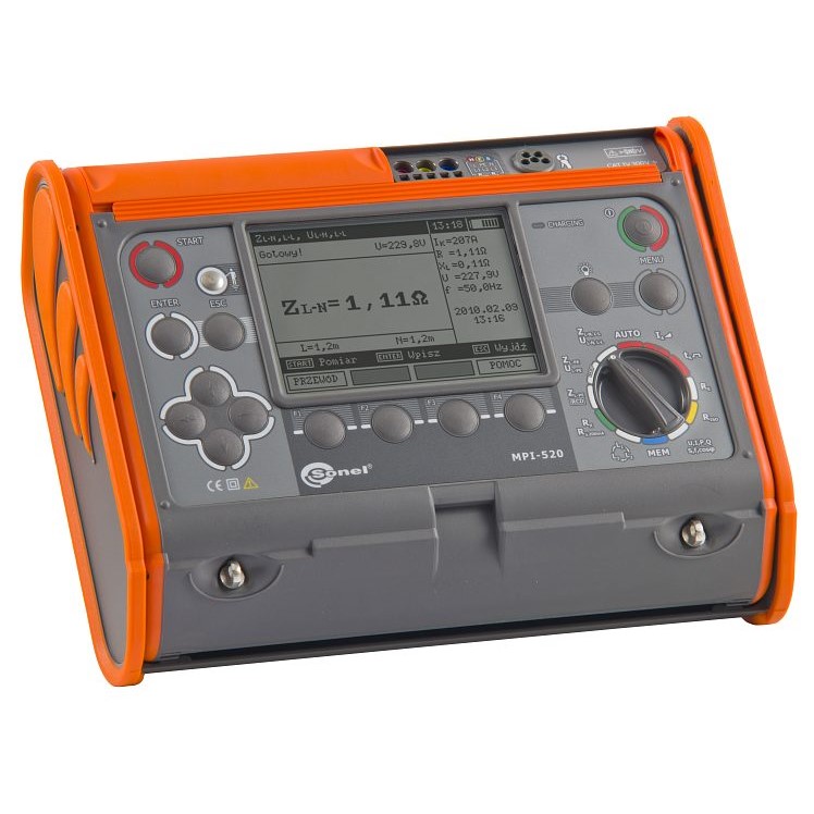
Description Electrical Installation Multi-function Meter MPI-520 Technical Specifications Possible measurements: Short-circuit loop measurement: Impedance measurement with 23 A current (44 A phase-to-phase) – short-circuit resistor R = 10 Ω Measurement range: 95 – 440 V, frequency 45 – 65 Hz Short-circuit loop measurement with resolution 0,01 Ω, in distribution network without triggering RCD (IΔn≥30 mA): Automatic calculation of short-circuit, detection of phase voltage and phase-to-phase voltage Additional UNI-Schuko plug for automatic measurement, AGT adapter for 3 phase network measurement Testing of general and selective RCD with the rated differential current of 10,30,100,300,500 And 1000 mA. (Type AC, A, and B). Measurement of insulation resistance: With test voltage 250 V, 500 V, 1000 V Measurement range up to 3 GΩ UNI-Schuko plug for insulation measurement Automatic discharging after measurement Automatic measurement of all resistances in 3,4,5-wire cables using optional adapter AUTO-ISO Acoustic signals in 5-sec intervals for insulation resistance characteristic Safety measurement – protection against overvoltage Measurement of earthing resistance. Bi-directional testing of PE wire continuity using 200 mA current. Autocalibration of test leads Phase sequence testing. Memory is divided into 10 memory banks each of them containing 99 memory cells. Battery charge indicator. AUTO-OFF function. USB interface. Rated operational conditions: – Operation temperature 0 – 50°C Electric security: – Type of insulation: double, according to PN-EN 61010 – 1 And IEC 61557, EMC – Measurement category: IV 300 V acc. to PN-EN 61010 – 1 – Protection class acc. to PN-EN 60529: IP54 Measurement of short circuit loop impedance ZL-PE, ZL-N, ZL-L Test current: 23/40 A; Measuring range acc. to IEC 61557: 0,13 – 1999,9 Ω (for 1.2 m test lead): Display range Resolution Accuracy 0,000 – 19,99 Ω 0,01 Ω ±(5% m.v. 3 digits) 20,00 – 199,9 Ω 0,1 Ω ±(5% m.v. 3 digits) 200,0 – 1999 Ω 1 Ω ±(5% m.v. 3 digits) Rated voltage: 95 – 270 V (for ZL-PE and ZL-N) and 95 – 440 V (for ZL-L) Frequency: 45 – 65 Hz Measurement of short circuit loop impedance ZL-PE in RCD mode Test current: 15 mA, measuring range acc. to IEC 61557: 0,50 – 1999 Ω Display range Resolution Accuracy 0,00 – 19,99 Ω 0,01 Ω ±(6% m.v. 10 digits) 20,0 – 199,9 Ω 0,1 Ω ±(6% m.v. 5 digits) 200 – 1999 Ω 1 Ω ±(6% m.v. 5 digits) Rated voltage: 95 – 270 V Frequency: 45 – 65 Hz Measurement of earth resistance RE Measuring range acc. to IEC 61557-5: 0,50 Ω -1999 Ω Display range Resolution Accuracy 0,00 – 9,99 Ω 0,01 Ω ±(2% m.v. 4 digits) 10,0 – 99,9 Ω 0,1 Ω ±(2% m.v. 3 digits) 100 – 999 Ω 1 Ω ±(2% m.v. 3 digits) 1,00 – 1,99 kΩ 0,01 kΩ ±(2% m.v. 3 digits) Insulation resistance measurements Measuring range acc. to IEC 61557-2: For UN= 50 V: 50 kΩ- 250 MΩ UN = 100 V: 100 kΩ – 500 MΩ UN = 250 V: 250 kΩ – 999 MΩ For UN = 500 V: 500 kΩ – 2 GΩ UN = 1000 V: 1 MΩ – 3 GΩ Display range * Resolution Accuracy 0,00 – 1999 kΩ 1 kΩ ±(3% m.v. 8 digits) 2,00 – 19,99 MΩ 0,01 MΩ ±(3% m.v. 8 digits) 20,0 – 199,9 MΩ 0,01 MΩ ±(3% m.v. 8 digits) 200 – 999 MΩ 1 MΩ ±(3% m.v. 8 digits) 1,00 – 3,00 GΩ 0,01 GΩ ±(4% m.v. 6 digits) 3,00 – 9,99 GΩ 0,1 GΩ ±(4% m.v. 6 digits) *Limited to measurement range. -With UNI-Schuko additional error ±2 % Phase sequence – Phase sequence indicator: forward, reverse – Mains voltage range UL-L: 100 – 440 V (45 – 65 Hz) UL-L: 100 – 440 V (45 – 65 Hz) – Display of phase-to-phase voltages Measurement of the active P, passive Q, and apparent S power and cosφ Range of voltages ULN: 0 – 440 V Nominal frequency of the network: 45 – 65 Hz Frequency measurement for voltage 50 – 440 V in range 45,0 – 65,0 Hz (accuracy max. ± 0,1%m.v. 1 digit) – Measurement cosφ: 0,00 – 1,00 (resolution 0,01) Low-voltage test of the circuit and insulation continuity Test of PE wire continuity using ±200 mA current Display range Resolution Accuracy 0,00 – 19,99 Ω 0,01 Ω ±(2% m.v. 3 digits) 20,0 – 199,9 Ω 0,1 Ω ±(2% m.v. 3 digits) 200 – 400 Ω 1 Ω ±(2% m.v. 3 digits) Voltage on open terminals: 4 – 9 V Test current at R < 2 Ω: min. 200 mA at rated battery voltage Autocalibration of test leads Measurements for both polarizations of the current RCD trigger and response time test tA(for tA mode): Measurement ranges in accordance with IEC 61557: 0 ms – up to the upper bound of the displayed value Breaker Type Test Current Multiplier Range Resolution Accuracy Standard 0,5*IΔn 0 – 300 ms 1 ms ±(2% m.v. 2 digits) Standard 1*IΔn 0 – 300 ms 1 ms ±(2% m.v. 2 digits) Standard 2*IΔn 0 – 150 ms 1 ms ±(2% m.v. 2 digits) Standard 5*IΔn 0 – 40 ms 1 ms ±(2% m.v. 2 digits) Selective 0,5*IΔn 0 – 500 ms 1 ms ±(2% m.v. 2 digits) Selective 1*IΔn 0 – 200 ms 1 ms ±(2% m.v. 2 digits) Selective 2*IΔn 0 – 200 ms 1 ms ±(2% m.v. 2 digits) Selective 5*IΔn 0 – 150 ms 1 ms ±(2% m.v. 2 digits) Precision of the differential current: for 0,5*IΔn:-8 – 0% | for 1*IΔn | 2*IΔn | 5*IΔn: 0 – 8% Measurement of the RCD triggering current (IA) for sine waveform testing current Selected current Meas. range Resolution Test current Accuracy 10 mA 3,3 – 10,0 mA 0,1 mA 0,3 x IΔn – 1,0 x IΔn ± 5% IΔn 30 mA 9,0 – 30,0 mA 0,1 mA 0,3 x IΔn – 1,0 x IΔn ± 5% IΔn 100 mA 33 – 100 mA 1 mA 0,3 x IΔn – 1,0 x IΔn ± 5% IΔn 300 mA 90 – 300 mA 1 mA 0,3 x IΔn – 1,0 x IΔn ± 5% IΔn 500 mA 150 – 500 mA 1 mA 0,3 x IΔn – 1,0 x IΔn ± 5% IΔn 1000 mA 330 – 1000 mA 1 mA 0,3 x IΔn – 1,0 x IΔn ± 5% IΔn It is possible to start the measurement from the positive or negative half of the forced leaking current Measurement of RCD tripping current (IA) for a unidirectional half-period sine waveform test current with a 6 mA DC offset Selected current Meas. range Resolution Test current Accuracy 10 mA 4 – 20,0 mA 0,1 mA 0,4 x IΔn – 2,0 x IΔn ±10%IΔn 30 mA 12,0 – 42,0 mA 0,1 mA 0,4 x IΔn – 1,4 x IΔn ±10%IΔn 100 mA 40,0 – 140 mA 1 mA 0,4 x IΔn – 1,4 x IΔn ±10%IΔn 300 mA 120 – 420 mA 1 mA 0,4 x IΔn – 1,4 x IΔn ±10%IΔn 500 mA 200 – 700 mA 1 mA 0,4 x IΔn – 1,4 x IΔn ±10%IΔn Measurement is possible for positive or negative forced leakage current Measurement of RCD triggering current (IA) for direct testing current Selected current Meas. range Resolution Test current Accuracy 10 mA 4 – 20,0 mA 0,1 mA 0,4 x IΔn – 2,0 x IΔn ±10%IΔn 30 mA 12,0 – 42,0 mA 0,1 mA 0,4 x IΔn – 2,0 x IΔn ±10%IΔn 100 mA 40,0 – 140 mA 1 mA 0,4 x IΔn – 2,0 x IΔn ±10%IΔn 300 mA 120 – 420 mA 1 mA 0,4 x IΔn – 2,0 x IΔn ±10%IΔn 500 mA 200 – 700 mA 1 mA 0,4 x IΔn – 2,0 x IΔn ±10%IΔn Measurement is possible for a positive or negative forced leakage current Calibration certificates are issued during the production process. New calibration certificates are available upon request at an additional cost. NOTE: “m.v.” – measured value.