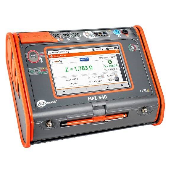
Description Multi-function Electrical Installation Meter | MPI-540 Measurement of short circuit loop impedance ZL-PE, ZL-N, ZL-L Test current: 23/40A; measuring range acc. to IEC 61557: 0,13…1999,9 Ω (for 1.2m test lead): Display range Resolution Accuracy 0,000…19,999 Ω 0,001 Ω ±(5% of reading 30 digits) 20,00…199,99 Ω 0,01 Ω ±(5% of reading 30 digits) 200,0…1999,9 Ω 0,1 Ω ±(5% of reading 30 digits) rated voltage: 95…270 V (for ZL-PE and ZL-N) and 95…440 V (for ZL-L) frequency: 45…65 Hz Measurement of short circuit loop impedance ZL-PE in RCD mode Test current: 15mA, measuring range acc. to IEC 61557: 0,50…1999 Ω Display range Resolution Accuracy 0,00…19,99 Ω 0,01 Ω ±(6% of reading 10 digits) 20,0…199,9 Ω 0,1 Ω ±(6% of reading 5 digits) 200…1999 Ω 1 Ω ±(6% of reading 5 digits) rated voltage: 95…270 V frequency: 45…65 Hz Measurement of earth resistance RE with the 3p and 4p method Measuring range acc. to IEC 61557-5: 0,50 Ω…1,99 k Ω for test voltage 50 V 0,56 Ω …1,99 k Ω for test voltage 25 V Display range Resolution Accuracy 0,00…9,99 Ω 0,01 Ω ±(2% of reading 4 digits) 10,0…99,9 Ω 0,1 Ω ±(2% of reading 3 digits) 100…999 Ω 1 Ω ±(2% of reading 3 digits) 1,00…1,99 kΩ 0,01 kΩ ±(2% of reading 3 digits) test voltage: 25 V or 50 V rms test current: 20 mA, sinusoidal rms 125 Hz (for fn = 50 Hz) and 150 Hz (for fn = 60 Hz) measurement blocked at interference voltage UN > 24 V maximum measured interference voltage Unmax = 100 V maximum resistance of auxiliary earth electrodes 50 kΩ Selective earth resistance measurement with clamp (3p clamp) Measuring range acc. to IEC 61557-5: 1 Ω…1,99 kΩ Display range Resolution Accuracy 0,00…9,99 Ω 0,01 Ω ±(2% of reading 4 digits) 10,0…99,9 Ω 0,1 Ω ±(2% of reading 4 digits) 100…999 Ω 1 Ω ±(2% of reading 4 digits) 1,00…1,99 kΩ 0,01 kΩ ±(2% of reading 4 digits) measurement with additional current clamp interference current measuring range: up to 9,99 A Selective earth measurement with two clamps Display range Resolution Accuracy 0,00…9,99 Ω 0,01 Ω ±(10% of reading 4 digits) 10,0…19,9 Ω 0,1 Ω ±(10% of reading 4 digits) 20,0…99,9 Ω 0,1 Ω ±(20% of reading 4 digits) measurement with transmitting and receiving clamps interference current measuring range: up to 9,99 A Soil resistivity measurement (ρ) Display range Resolution Accuracy 0,00…9,99 Ω 0,01 Ω ±(2% of reading 4 digits) 10,0…99,9 Ω 0,1 Ω ±(2% of reading 4 digits) 100…999 Ω 1 Ω ±(2% of reading 4 digits) 1,00…1,99 kΩ 0,01 kΩ ±(2% of reading 4 digits) measurement with Wenner’s method distance settable in metres or feet distance range: 1…30 m (1…90 feet) Phase sequence indication phase sequence indication: conforming, non-conforming mains voltage range U : 100…440 V (45…65 Hz) L-L display of phase-to-phase voltage values Measurements of RCD parameters (voltage range 95…270 V): RCD tripping test and measurement of tripping time tA (for tA measurement function) RCD type Current Range Resolution Accuracy General and short-time delay 0,5*IΔn 0…300 ms 1 ms ±(2% of reading 2 digits) (for RCD with IΔn=10 mA and 0,5xIΔn uncertainty: ±(2% of reading 3 digits) General and short-time delay 1*IΔn 0…300 ms 1 ms ±(2% of reading 2 digits) (for RCD with IΔn=10 mA and 0,5xIΔn uncertainty: ±(2% of reading 3 digits) General and short-time delay 2*IΔn 0…150 ms 1 ms ±(2% of reading 2 digits) (for RCD with IΔn=10 mA and 0,5xIΔn uncertainty: ±(2% of reading 3 digits) General and short-time delay 5*IΔn 0…40 ms 1 ms ±(2% of reading 2 digits) (for RCD with IΔn=10 mA and 0,5xIΔn uncertainty: ±(2% of reading 3 digits) Selective 0,5*IΔn 0…500 ms 1 ms ±(2% of reading 2 digits) (for RCD with IΔn=10 mA and 0,5xIΔn uncertainty: ±(2% of reading 3 digits) Selective 1*IΔn 0…200 ms 1 ms ±(2% of reading 2 digits) (for RCD with IΔn=10 mA and 0,5xIΔn uncertainty: ±(2% of reading 3 digits) Selective 2*IΔn 0…200 ms 1 ms ±(2% of reading 2 digits) (for RCD with IΔn=10 mA and 0,5xIΔn uncertainty: ±(2% of reading 3 digits) Selective 5*IΔn 0…150 ms 1 ms ±(2% of reading 2 digits) (for RCD with IΔn=10 mA and 0,5xIΔn uncertainty: ±(2% of reading 3 digits) accuracy of residual current application: for 0,5*IΔn:-8…0% for 1*IΔn, 2*IΔn, 5*IΔn: 0…8% measurement of RCD tripping current IΔn for sinusoidal residual current (AC type) Rated current Meas. range Resolution Test current Accuracy 10 mA 3,3…10,0 mA 0,1 mA 0,3 x IΔn…1,0 x IΔn ± 5% IΔn 30 mA 9,0…30,0 mA 0,1 mA 0,3 x IΔn…1,0 x IΔn ± 5% IΔn 100 mA 33…100 mA 1 mA 0,3 x IΔn…1,0 x IΔn ± 5% IΔn 300 mA 90…300 mA 1 mA 0,3 x IΔn…1,0 x IΔn ± 5% IΔn 500 mA 150…500 mA 1 mA 0,3 x IΔn…1,0 x IΔn ± 5% IΔn 1000 mA 330…1000 mA 1 mA 0,3 x IΔn…1,0 x IΔn ± 5% IΔn the measurement can be started from positive or negative half-period of forced leakage current (AC) Measurement of RCD tripping current IA for unidirectional residual current and unidirectional with the 6 mA DC bias (type A) Rated current Meas. range Resolution Test current Accuracy 10 mA 3,5…20,0 mA 0,1 mA 0,35 x IΔn…2,0 x IΔn ± 10% IΔn 30 mA 10,5…42,0 mA 0,1 mA 0,35 x IΔn…1,4 x IΔn ± 10% IΔn 100 mA 35…140 mA 1 mA 0,35 x IΔn…1,4 x IΔn ± 10% IΔn 300 mA 105…420 mA 1 mA 0,35 x IΔn…1,4 x IΔn ± 10% IΔn 500 mA 175…700 mA 1 mA 0,35 x IΔn…1,4 x IΔn ± 10% IΔn measurement for positive or negative half-periods of forced leakage current Measurement of RCD tripping current I for direct residual current (type B) Rated current Meas. range Resolution Test current Accuracy 10 mA 2,0…20,0 mA 0,1 mA 0,2 x IΔn…2,0 x IΔn ± 10% IΔn 30 mA 6…60 mA 1 mA 0,2 x IΔn…2,0 x IΔn ± 10% IΔn 100 mA 20…200 mA 1 mA 0,2 x IΔn…2,0 x IΔn ± 10% IΔn 300 mA 60…600 mA 1 mA 0,2 x IΔn…2,0 x IΔn ± 10% IΔn 500 mA 100…1000 mA 1 mA 0,2 x IΔn…2,0 x IΔn ± 10% IΔn measurement for positive or negative half-periods of forced leakage current IΔn – rated residual current Insulation resistance measurements Measuring range acc. to IEC 61557-2: for Un = 50 V: 50 kΩ…250 MΩ for Un = 100 V: 100 kΩ…500 MΩ for Un = 250 V: 250 kΩ…999 MΩ for Un = 500 V: 500 kΩ…2 GΩ for Un = 1000 V: 1 MΩ…9,99 GΩ Display range *) Resolution Accuracy 0,00…9,99 Ω 0,01 Ω ±(3% of reading 8 digits) 10,0…19,9 Ω 0,1 Ω ±(3% of reading 8 digits) 20,0…99,9 Ω 0,1 Ω ±(3% of reading 8 digits) 20,0…99,9 Ω 0,1 Ω ±(3% of reading 8 digits) 20,0…99,9 Ω 0,1 Ω ±(4% of reading 6 digits) *) not greater than measuring range for given voltage Low-voltage measurement of resistance and circuit continuity Measurement of protective conductor continuity with the ±200 mA current Display range Resolution Accuracy 0,00…19,99 Ω 0,01 Ω ±(2% of reading 3 digits) 20,0…199,9 Ω 0,1 Ω ±(2% of reading 3 digits) 200…400 Ω 1 Ω ±(2% of reading 3 digits) voltage on open terminals: 4…9 V output current at R < 2 Ω: min. 200 mA autocalibration of test leads measurements for both current polarities Illuminance measurement Display range Resolution Accuracy 0,1…99,9 lx 0,1 lx ±(5% of reading 2 digits) 100…999 lx 1 lx ±(5% of reading 2 digits) 1,00…9,99 klx 0,01 klx ±(5% of reading 2 digits) 10,0…19,9 klx 0,1 klx ±(5% of reading 2 digits) measurement in luxes (lx) or feet-candles (fc) Three-phase recorder of electrical network parameters The device is designed to work with networks: with nominal frequency 50/60 Hz with nominal voltage: 64/110 V 110/190 V 115/200 V 127/220 V 220/380 V 230/400 V 240/415 V 254/440 V 290/500 V DC network Supported networks: single-phase two-phase with common N conductor, three-phase star connection N with and without conductor three-phase delta Parameters of analyzer: Parameter Measurement range Max. resolution Accuracy Alternating voltage (TRMS) – 0,0…500 V 0,01 % Unom ±0,5% Unom Alternating current TRMS – depending on clamp* 0,01% Inom ±2% of reading for reading of ≥ 10% Inom ±2% Inom for reading of < 10% Inom (error does not account for clamps error) Frequency – 40,00…70,00 Hz 0,01 Hz ±0,05 Hz Active, reactive, apparent and distortion power – depending of configuration (transformers, clamp) up to for decimal places depending of configuration (transformers, clamp) Active, reactive apparent energy – depending of configuration (transformers, clamp) up to for decimal places as power error cosφ and power factor (PF – 0,00…1,00 0,01 ±0,03 Harmonics Voltage as for alternating voltage as for alternating voltage ±5% of reading for reading of ≥ 3% Unom ±0,15% Unom for reading of < 3% Unom Harmonics Current as for alternating voltage as for alternating voltage ±5% of reading for reading of ≥ 10% Inom ±0,5% Inom for reading of < 10% Inom THD Voltage 0.0…100.0% (in regards to the rms value) 0,1% ±5% THD Current 0.0…100.0% (in regards to the rms value) 0,1% ±5% Voltage asymmetry Voltage and current 0,0…10,0% 0,1% ±0,15% (absolute error) * Clamp F-1A, F-2A, F-3A: 0..3000 A (10000 Ap-p ) * Clamp C-4A: 0..1000 A (3600 Ap-p ) * Clamp C-5A: 0..1000 A (3600 Ap-p ) * Clamp C-6A: 0..10 A (36 Ap-p ) * Clamp C-7A: 0…100 A (360 Ap-p ) Clamps C-4A WACEGC4AOKR C-5A WACEGC5AOKR C-6A WACEGC6AOKR C-7A WACEGC7AOKR F-1A WACEGF1AOKR F-2A WACEGF2AOKR F-3A WACEGF3AOKR Rated current 1000 A AC 1000 A AC 1400 A DC 0 A AC 100 A AC 3000 A AC 3000 A AC 3000 A AC Max. overload current 1200 A AC 1000 A AC 3000 A DC 20 A AC 100 A AC 10k A AC 10k A AC 10k A AC Minimal measurable current 100 mA 500 mA 10 mA 20 mA 1 A 1 A 1 A Frequency 30 Hz…10 kHz DC…5 kHz 40 Hz…10 kHz 40 Hz…1 kHz 40 Hz…10 kHz 40 Hz…10 kHz 40 Hz…10 kHz Imput signal level 1 mV / 1 A 1 mV / 1 A 100 mV / 1 A 500 mV / 1A 38,8 μV / 1 A 38,8 μV / 1 A 38,8 μV / 1 A Max. diameter of measured cord 52 mm 39 mm 20 mm 24 mm 360 mm 235 mm 120 mm Minimal basic accuracy ≤0,5% ≤1,5% ≤1% 0,5% 1% 1% 1% Battery power supply — — — — — — Lead length 2,2 m 2,2 m 2,2 m 3 m 2,2 m 2,2 m 2,2 m Measurement category IV 300 V IV 300 V IV 300 V III 300 V IV 600 V IV 600 V IV 600 V Multi-function Electrical Installation Meter | MPI-540